Hardware configuration and connection are very important if you want this to work.
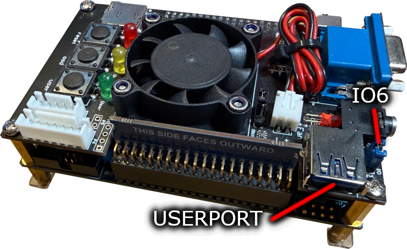
The MiSTer floppy board connects to the USER PORT on the I/O board (Analog I/O Board V6.1, Digital I/O Board 1.2 or later revisions). Next to the USER PORT should be a jumper IO6, and the jumper MUST be in IO6 position for this to work. Some boards have missing pins or are badly made, so you may need to check and order from a reputable source.
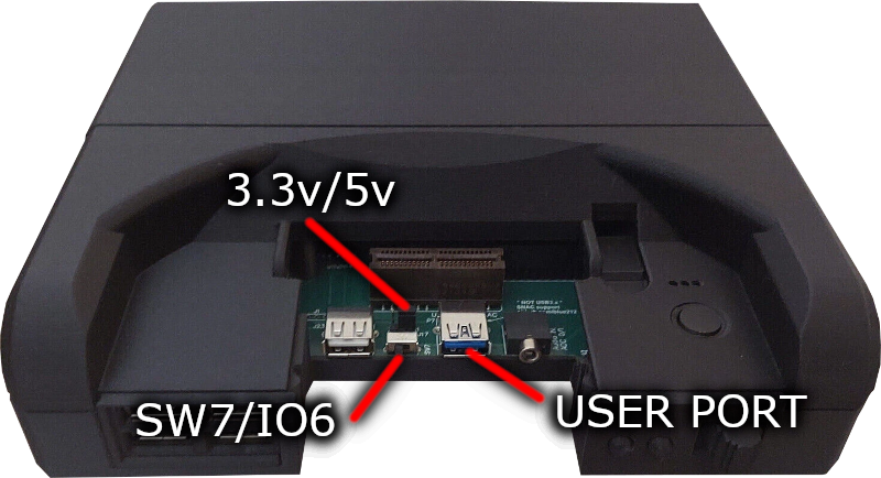
The MiSTer floppy board connects to the USER PORT at the front of the unit, behind the removable panel. Switch SW7/IO6 needs to be slid to the left into IO6 mode, and I recommend leaving the 3.3V/5V slider in the 5V position.
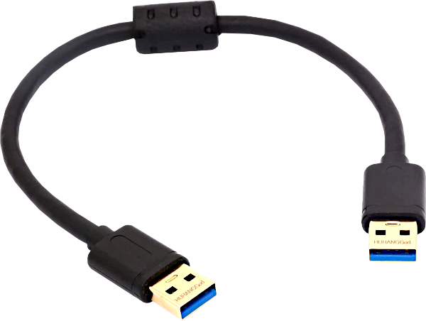
You need to use a special type of USB3 cable to connect MiSTer Floppy. It should work with any of the compatible cables used by the MT32-Pi.
I have tested this cable and this cable and they work properly. The most important feature is the length of the cable, and it should be as short as possible, both of these are 0.3m long (approx 12 inch/1 ft) I have had some success with 0.5m cables but I don't recommend them.
Also, not all USB3 cables are wired the same. MiSTer floppy supports two variants and will adjust for these automatically but there is a third type that will not work.
Your MiSTer can provide 5V to the MiSTer Floppy, and depending on a jumper setting will power your floppy drive too. However, this may not always be a good idea. The MiSTer Floppy board includes a 500mA auto-resetting fuse to prevent damage, but you still may want to use an external supply:
I Strongly Recommend Using an External 5V Supply
To power the drive externally you have two options. First you can simply connect the connector on the back of the floppy drive to another power supply. Secondly, you can use the included barrel jacks on the board to hook up another supply. A suitability powered USB supply should be ok with a suitable cable, available from many retailers.
SMD PCB
Thru-Hole PCB
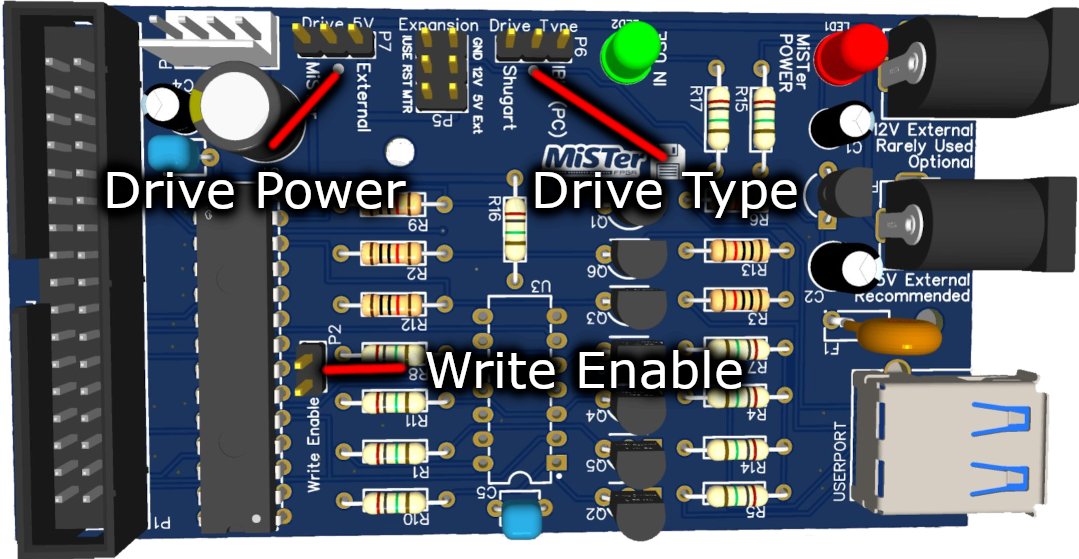
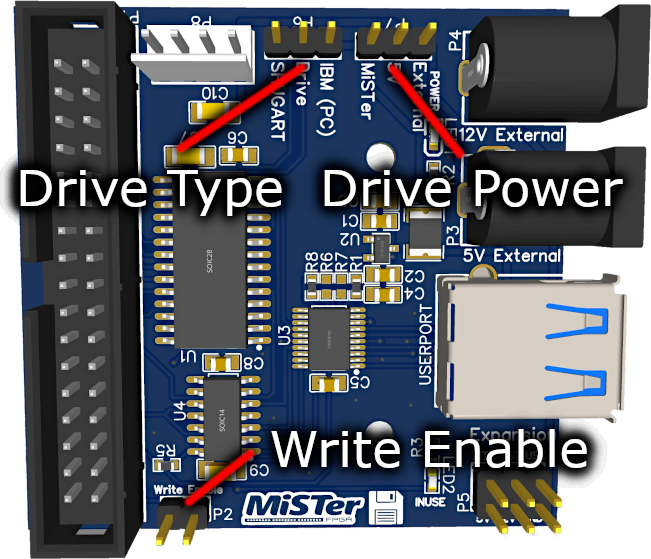
Drive Type
Drive Power
Write Enable
Floppy drives are getting old. I've even had some where the switch that detects write protect was broken making the disk always appear write enabled! If you remove this jumper it physically prevents the drive from entering into writing mode.
The operating system can't tell the difference except nothing will actually be saved and therefore verify will fail.
If you aren't planning on writing to disks, I strongly recommend disconnecting this jumper to be 100% sure that your disks remain intact! Besides, viruses are still a thing 😊
![]()
Original MiSTer-kun Cat by hewhoisred and MiSTer Logo by Conrad Fenech
Website & MiSTer Floppy Copyright © 2022-2026 RobSmithDev | Terms and Conditions | Privacy Policy

